
XPI-3568 microcomputer,microcontroller, Single-board computer, Main control board
Appication:Ev charger, automatic machinery and equipment, robots, gateways etc
1. GENERAL DESCRIPTION
The XPI-3568 is a microcomputer product of Raspberry Pi form factor developed by Geniatech based on the RockChip 3568J platform. According to the definition of Raspberry Pi, this is suitable for the field of programming education for teenagers , robotics, Commercial display industry and media play box and so on..
This product’s key features including a RockChip high-performance and low power quad-core application 64-bit quad-core processor, HDMI display supports up to 4KP60 resolutions, XPI-3568 supports almost full-format H.264/H.265 decoder by 4K@60fps, also support H.264/H.265 encoder by 1080p@60fps, high-quality JPEG encoder/decoder. Up to 8GB of RAM, dual-band 2.4/5.0 GHz wireless LAN, Bluetooth 4.0, Gigabit Ethernet, USB 3.0 and USB 2.0.
Below is the detailed specification
(I) 85mm*56mm, Only the size of a bank card
(II) RockChip RK3566/RK35668J with Quad-core Cortex-A55 up to 1.8GHz
(III) Up to 8G RAM, 128GB eMMc flash
(IV) USB HOST 3.0 * 1 ,USB Host 2.0*2 ,USB OTG 3.0*1, 1*HDMI Out, 1*Type-C, 1*UART for debug, 1* Extension GPIO interface
(V) Support Android 11.0 or Linux (Debian 10/ Raspbian OS emulation)
(VI) Wi-Fi and 1000M LAN interface
(VII) Micro SD card (TF card: Max64G)
(VIII)Provide open-source code and hardware schematics
(IX) The product has a long-life cycle and can be supplied over 10 years
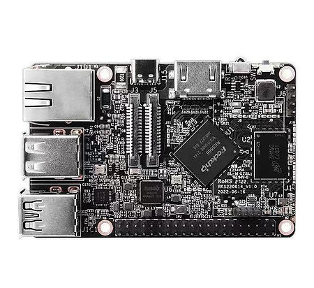
2. PRODUCT OVERVIEW
Below picture is for reference only, please prevail in kind.

Name
RK3568J SOC
LPDDR4
USB Connector
40 Pin GPIO header
MIPI CSI Connector
MIPI DSI Connector
USB double layer connector
USB2.0 double layer connector
RJ45
DC IN
SW1
HDMI Connector
IR
SW2
A55 Core debug console
eMMC Flash
Micro SD card Slot
Description
*1
*1
* 1(It can be used for Wi-Fi/BT port)
*1
*1
*1
* 1(The upper interface of J1 supports OTG function, the bottom interface of J1 supports USB 3.0 function)
*1
* 1( 10/100/1000Mbps)
* 1(5V/3A USB Type-C)
* 1(Power on key)
* 1(up to 4KP60)
*1
* 1(Recovery Key)
*1
*1
*1
3. FEATURES
CHIPSET
MARKET AREA
Processor
NETWORK
Interface
Connectivity
Adapter
Dimensions
RK3568/RK3568J
Global
OS
CPU
GPU
NPU
LPDDR4
EMMC FLASH
Android 11/Debian 10/Raspbian OS emulation
Quad-core ARM Cortex-A55 CPU up to 1.8GHz
ARM G52 2EE GPU;Supports OpenGL ES 1.1/2.0/3.2. OpenCL 2.0. Vulkan 1.1
Embedded high-performance 2D acceleration hardware
Integrated RKNN NPU AI accelerator, 1Tops@INT8 Supports one-click switching of
Caffe/TensorFlow/TFLite/ONNX/PyTorch/Keras/Darknet
2GB(1G/4G/8G optional)
8GB eMMC5.1(8-128GB Optional)
Ethernet
WiFi
Bluetooth
HDMI Out
USB 3.0
USB 2.0
MIPI-CSI
MIPI-DSI
Micro SD slot
IR
DC IN
RJ45, 10/100/1000M
WIFI Module 2.4G/5.8G (optional)
BT4.0(integrated in the WiFi module)
*1
*2(USB Host 3.0*1 ,USB OTG 3.0*1)
*2(USB Host 2.0*2)
*1
*1
*1
*1
*1 (USB Type-C)
1x Standard 40-pin GPIO header
• Can be expanded to UART, SPI, I2C ,PWM function
1x4 pin USB-Wifi connector
• Support USB-WiFi Module
1x MIPI DSI
• 4-lane MIPI DSI display port
1x MIPI CSI
• 2-lane MIPI CSI camera port
DC 5V / 3A
85*56mm
4. HARDWARE BLOCK

5. Connectors Definition
5.1 MIPI CSI Connector (J24)

Pin
1
2
3
4
5
6
7
8
Definition
GND
MIPI_CSI_RX_D0N
MIPI_CSI_RX_D0P
GND
MIPI_CSI_RX_D1N
MIPI_CSI_RX_D1P
GND
MIPI_CSI_RX_CLK0N
Pin
9
10
11
12
13
14
15
16~30
Definition
MIPI_CSI_RX_CLK0P
GND
PCIE20 _ CLKREQn _ M
NC
I2C1 _ SCK _ C
I2C1 _ SDA _ C
VDDIO _ 3.3V
NC
5.2 MIPI DSI Connector(J23)
Pin
1
2
3
4
5
6
7
8
9
10
11
12
13
14
15
Definition
GND
MIPI _ TX0 _ D1N
MIPI _ TX0 _ D1P
GND
MIPI _ TX0 _ CLKN
MIPI _ TX0 _ CLKP
GND
MIPI _ TX0 _ D0N
MIPI _ TX0 _ D0P
GND
I2C2 _ SCK _ D
I2C2 _ SDA _ D
GND
VDDIO _ 3.3V
VDDIO _ 3.3V
Pin
30
29
28
27
26
25
24
23
22
21
20
19
18
17
16
Definition
NC
MIPI _ TX0 _ D2P
MIPI _ TX0 _ D2N
NC
MIPI _ TX0 _ D3P
MIPI _ TX0 _ D3N
NC
NC
SARADC _ VIN2 _ LCD _ I
NC
NC
NC
NC
NC
NC

5.3 USB Connector for Wi-Fi(J26)

Pin
1
2
Definition
VCC5V0 _ USB
USB2_HOST2_DM
Pin
3
4
Definition
USB2_HOST2_DP
GND
5.4 40 Pin GPIO header (J22)
Pin
1
3
5
7
9
11
13
15
17
19
21
23
25
27
29
31
33
35
37
39
Definition
VDDIO_3.3V
I2C5_SDA_M0/GPIO3_B3_D
I2C5_SCL_M0/GPIO3_B4_D
I2S1_MCLK_M1/GPIO3_C6_D
GND
SPI3 _ CLK _ M0/GPIO4_B3_D
SPI3 _ MOSI _ M0/GPIO4_B2_D
SPI3 _ MISO _ M0/GPIO4_B0_D
VDDIO_3.3V
SPI2_MOSI_M1/GPIO2_D6_D
SPI2_MISO_M1/GPIO2_D7_D
SPI2_CLK_M1/GPIO3_A0_D
GND
I2C2_SDA_M1/GPIO4_B4_D
SPI3_CS0_M0/GPIO4_A6_D
SPI3_CS1_M0/GPIO4_A7_D
UART4_RX_M1_PWM/GPIO3_B1_D
I2S1_LRCK_TX_M1/GPIO3_D0_D
UART3_TX_M1/GPIO3_B7_D
GND
Pin
2
4
6
8
10
12
14
16
18
20
22
24
26
28
30
32
34
36
38
40

Definition
VCC5V0_SYS
VCC5V0_SYS
GND
UART1_TX_M1/GPIO3_D6_D
UART1_RX_M1/GPIO3_D7_D
I2S1 _ SCLK _ TX _ M1/GPIO3_C7_D
GND
UART1_CTSn_M1/GPIO4_C1_D
UART1_RTSn_M1/GPIO4_B6_D
GND
GPIO3_C4_PWM
SPI2_CS0 _M1/GPIO2_D5_D
SPI2_CS1_M1/GPIO2_D4_D
I2C2_SCL_M1/GPIO4_B5_D
GND
UART4_TX_M1_PWM/GPIO3_B2_D
GND
UART3_RX_M1/GPIO3_C0_D
I2S1_SDI0_M1/GPIO3_D2_D
I2S1_SDO0_M1/GPIO3_D1_D
5.5 Cortex Debug UART Connector (J25)

Pin
1
2
Definition
VCC3V3 _ PM
UART2_TX_M0_DEBUG
Pin
3
4
Definition
UART2_RX_M0_DEBUG
GND
6. SUPPORT FORMATS
Audio
-
Video Decoder
-
I2S0 with 8 channel
-
Up to 8 channels TX and 8 channels RX path
-
Audio resolution from 16bits to 32bits
-
Sample rate up to 192KHz
-
Provides master and slave work mode, software configurable
-
Support 3 I2S formats (normal, left-justified, right-justified)
-
Only for HDMI inside
-
I2S1 with 8 channel
-
Up to 8 channels TX and 8 channels RX path
-
Audio resolution from 16bits to 32bits
-
Sample rate up to 192KHz
-
Provides master and slave work mode, software configurable
-
Support 3 I2S formats (normal, left-justified, right-justified)
-
Support 4 PCM formats (early, late1, late2, late3)